
Potential Heave in the Pressed Concrete & Pressed Steel Piles in Residential Foundation Construction
By W. Tom Witherspoon, P.E.
(reprinted with permission)
 Tom Witherspoon is President of S&W Foundation Contractors, Richardson, Texas. He is a member of the ADSC’s Board of Directors and is chairman of the Scholarship Committee and Residential Foundation Committee. He is the past president of the National Foundation Repair Association (FRA). He is the author of Residential Foundation Performance. (Editor)
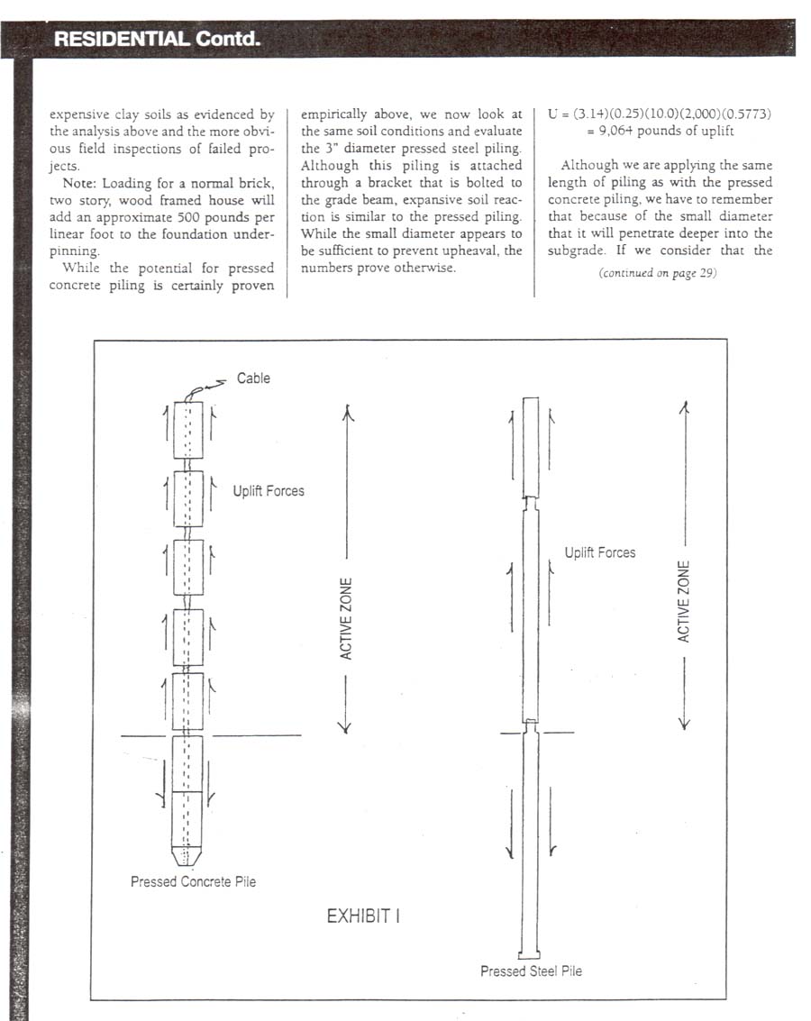
The perma-jack system was introduced in 1974 in Texas and consisted of an approximate 3″ diameter steel pipe that attached to the foundation grade beam with the aid of a steel bracket. The pipe was then driven into the soil using the weight of the house to a point that the house was lifted at that pile point or a predetermined pressure was achieved on the driving system. Several adaptations have been developed since that time, but the most notable of these driven systems has been the pressed concrete piling and the pressed steel piling (Exhibit 1).
The pressed steel piling system is very similar to the original perma-jack system in that it consists of steel pipe (approximately 3′ in diameter x approximately 4′ long) with a driving ring that is slightly larger than the pipe in order to reduce friction during the installation. There is also a bracket installed to the grade beam that helps reduce rotation forces from a pipe that sits along the exterior of the grade beam and provides a lock to secure the pipe against the grade beam after elevations adjustments have been achieved. Normal spacing will vary between 6′ and 10′ o.c.
The pressed concrete piling system is also a derivative of the perma-jack system but in this situation the piling material is concrete. The most typical concrete piling is a precast cylinder, an approximate 6″ in diameter and 12″ long with a 1″ hole through the length of the piling. The precast concrete cylinders are set into an excavated hole under the grade beam at spacing between 6′ and 10′ o.c. and then pressed downward using the weight of the house to advance the cylinders until the house is lifted at each piling point. On top of the pressed pile is a precast beam that will normally support the grade beam with two precast cylinders and metal shims to adjust the newly elevated grade beam. The precast concrete cylinders have an approximate 1″ diameter hole at the center that is either left open or a multi-strand cable is used that runs from a dead end at the bottom to the top cylinder. Although some companies will pour epoxy around the cable at the top cylinder, most contractors will merely cut-off at the top with the primary function being only to measure the depth of piles that have been advanced and provide minimal lateral stability. The initial precast cylinder is a driving shoe that is shaped like a Styrofoam cup that is used to anchor the cable and advance the piling system. This method of underpinning is very popular because of its quick installation (no concrete cure time is required on the concrete) and with a installation price that is normally much cheaper because of the great reduction in labor and material costs.
At first glance it would appear these methods would not be susceptible to upheaval and/or creep inducted swelling/heaving, because of the small diameter and subsequent lesser magnitude of skin friction. Recent investigations, however, have revealed cases where these piles have heaved significantly and lifted the house perimeter to cause measurable damage to the veneers, framing and door function. Therefore, a closer evaluation of the function of these piles in expansive clay soil is warranted.
The first shortcoming of the pressed concrete or steel piles is that they can seldom be set below the zone of seasonal moisture variation. Many clays in Texas, for instance, are highly plastic and have such high shear strengths that penetration with a 6″ diameter pile is very difficult and would exceed the driving weight. Consider that a typical house weighs approximately 1,000 pounds per foot at the perimeter and that is the only weight that can be engaged for installation. An added problem with concrete pressed piling is that much of Texas is in a semi-arid region that will go from very wet to very dry in a matter of a few months. When factoring in the drying of clays to depth that may exceed 12′, you have a strata that will not be penetrated below the active zone and certainly not far enough below to provide an anchor to resist upward pushing forces.
 Even if the piles can be driven below the active zone, a closer look at the system shows that even when the targeted depth is obtained, support is not advanced below the active zone because they are not connected. In the case of the concrete pressed pile the cable is seldom stressed/locked at the top, which allows each pile member to act more like cylindrical footings that a driven pile. In fact, the piles that rest in the active zone will life the push up the house without engaging any of the piles sections that may have been driven below this area of seasonal moisture change. The steel piling is no better as the connection is only a male/female slip connection with little or no tensile bond. (Exhibit 1)
Therefore, the result is segmental shafts that will lift the house without any tie-down resistance such as would be derived from a belled cast-in-place pier or even a cast-in-place pier that is merely extended below the active zone. To further degrade the value of these piles is the fact during heaving there will be a remolding of active clay below the bottom heaved pile and between piles that do not act as quickly that will remain between the piles when the active zone becomes dry. As a result, the piles will never be completely restored to the original integrity at the time of installation.
The segmental upheaval flaw is exposed by calculating uplift potential of the piles to counteract loading of the structure along the grade beam. The following equation is reorganized for calculation of uplift forces generated by a pier/pile in expansive clay soil:
U=(pi) Ds Z pt tanøps (Das 1984)
Although each site must be evaluated with proper soils information, for purposes of this exercise we will make the following assumptions based upon this engineer’s experience in the Dallas Metroplex in relation to the concrete pressed pile:
Ds = 0.5 feet (6″ diameter of the concrete pile)
Z = 10.0 feet (depth of the active zone)
Pt = 2,000 pounds per square feet (zero horizontal swell pressure)
Øps 30 degrees (effective angle of plinth-soil friction)
(Reference*U.S. Navy 1971)
Therefore:
U = (3.14)(0.5)(10.0)(2,000)(0.5773) = 18,127 pounds
Note: Drained friction angle measurements in North Texas are normally in the range of 23 degrees to 30 degrees. Therefore, the assumed 30 degree factor is not unfeasible.
When you assume a perimeter pile loading of approximately 6,000 pounds (1,000 pounds per linear feet x a proper spacing of 6′ o.c.) you have lifting of the foundation perimeter. Keep in mind that many houses are much less that 1,000 pounds per linear feet and that swell pressures in the more active areas are much higher that the assumed 2,000 p/sf. Therefore, this remedial repair method does not fit utilization in expensive clay soils as evidenced by the analysis above the more obvious field inspections of failed projects.
 Note: Loading for a normal brick, two story, wood framed house will add an approximate 500 pounds per linear foot to the foundation underpinning.
While the potential for pressed concrete piling is certainly proven empirically above, we now look at the same soil conditions and evaluate the 3″ diameter pressed steel piling. Although this piling is attached through a bracket that is bolted to the grade beam, expansive soil reaction is similar to the pressed piling. While the small diameter appears to be sufficient to prevent upheaval, the numbers prove otherwise.
U = (3.14)(0.25)(10.0)(2,000)(0.5773) = 9,064 pound of uplift
Although we are applying the same length of piling as with the pressed concrete piling, we have to remember that because of the small diameter that it will penetrate deeper into the subgrade. If we consider that the active zone in a semiarid area such as the Dallas/Fort Worth Metroplex of Texas will commonly create an active zone (zone of seasonal moisture variation) to depths over 12′, we have even greater potential for upheaval.
 U= (3.14)(0.25)(12)(2,000)(0.5773) = 10,877 pounds of uplift
Note: Input from local geotechnical engineers has revealed that swelling pressures in excess of 3,000 pounds per square foot have been measured in the metroplex (Irving, Texas) and that plinth-soil friction may be as high as 40 degrees as evidenced by the US Navy tests conducted in 1971. When you factor these potential ranges into the equation, it is obvious the calculations delineated above are somewhat conservative.
One other factor is that unlike the drilled shaft where material is removed, the driving action of the pile remolds the surrounding soil with increased density (particle packing) and lowering of moisture content. As a result, the pile is much more susceptible to uplift pressures when moisture levels return. (Bowles 1988)
Although the potential for pressed pile movement is certainly proven in the theoretical calculations delineated above, this writer has recently witnessed one house in Arlington, Texas where the pressed concrete pilings heaved the perimeter an approximate 3″. Confirmation of this occurrence was achieved when the pressed piling support was removed and the house settled back down to an even elevation. The second flaw of this system is that in expansive clay soils the shear strength and density of the stiff clay in this region cannot be penetrated below the active zone, especially in dry seasons. At the house witnessed by this writer, the repair contractor was only able to drive the piles to an average depth of 8′ prior to lifting the house at an individual piling. Remember, a house provides limited weight to push a piling and if the contractor attempts to push beyond the first lift of the house, damage to the grade beam and walls will surely occur. Confirmation of this has been confirmed with reports that the pressed concrete piles could only be driven to depths of 4′ to 5′ if attempted during a dry hot summer.
This author has also received information on approximately 12 houses in another area of Arlington, Texas where pressed steel pilings (3″ diameter) caused heaving of the houses and extensive litigation erupted. As a result, many of the previously underpinned houses had to be reworked with pilings that could resist upheaval action by the expansive clay soils of this region.
Although there is a problem setting pressed pilings below the active zone into strata that will provide adequate support, the primary problem is the fact that the piling are not attached and, therefore, cannot develop adequate hold-down pressures to counteract heaving clay forces. It is obvious that if the pressed pilings were attached with adequate reinforcement and could be driven deep far enough below the active zone to resist pull-out pressures, they would not contribute to foundation heaving. This penetration below this level is significant, however. In fact, the depth required below the active zone would need to be 20 times the shaft diameter. (Nelson & Miller 1992). This would necessitate the 6″ diameter concrete pile being 10′ below the active zone while the 3″ diameter steel would only have to be 5′ below this same zone of influence.
 Providing an ample amount of reinforcement, however, could prove to be a problem. In the steel piling a cable could be installed and tied off at the ends to provide some amount of tensile strength. A review of the elongation formula shows that in theory the deflection ? = PL/Ae where P = pulling pressure, L = length of cable, A = area of cable and e = modulus of elasticity for the steel cable. Interviews with field installers, however, reveals that there is much more elongation initially until the cable is fully engaged. Therefore, use of tied-off cables would only provide continuity of the pile unit after some amount of separation was achieved. As noted in the formula, the amount of elongation is dependent upon pressure and upon area of cable. With a 3/8″ cable, the elongation would be larger but this is predicated upon the cable being straight and tense prior to movement occurring. If the cable was merely tied-off, little resistance to stretching of the cable would be available until a significant amount of pressure was applied by upheaval pressure. Therefore, unless the cable was truly tensioned to a sizable load, a few inches of movement could occur, which would allow some upheaval in the active zone.
With concrete pilings, the problems would appear to be greater. First there is no good way to tension the cable without causing damage to the concrete cylinder. These cylinders are just not poured with design considerations for post tensioning. There is only a 1″ circular hole through the cylinders. Design engineers in this area of the Dallas/Fort Worth Metroplex know that a minimum 1% steel is required to prevent tensile failure in piers/piles and that the steel should be in the form of a cage to resist bending moments created by the cyclic moisture changes and other forces that are common supporting a house. For a 6″ diameter pier the required amount of steel would be .28″, which would equate to a 5/8″ bar set in the 1″ diameter hole. Now remember that these cylinders are set one at a time. Therefore, they would have to be lapped 25″ (40 bar diameter lap), and the center cavity would have to be increased in size to at least 1.5″ to clear the bars and gnarling. Now even if the reinforcing steel could be properly lapped, you have the added problem of grouting these bar sections to the concrete piles. Since the hole is cast in the concrete cylinders, it is normally smooth with little natural friction for a suitable bond. You then have the added problem that the pile will remain somewhat flexible to lateral forces that would certainly induce tensile moments around the pressed pile. With sectional reinforcement, questionable bonding capacity of the cavity grout and potential soil contamination during the process, the integrity of this alteration would be questionable at best.
 Although vertical stability is certainly questionable, as evidenced above, we have the additional factor of lateral stresses. Without ample reinforcement size and more importantly the location of this reinforcement; resistance to soil creep, slope action and other lateral forces certainly dictates that these pressed piling systems should not be installed in areas that are subjected to these actions.
As with any piling in cohesive soil, it is important that the piles be seated far enough into the termination strata that all friction forces stay engaged. It is also important that the initial driving force be continued until the targeted depth has been achieved so that a false bearing strength can be avoided that would provide support at a premature depth. In expansive (cohesive) soils there is a process called Thixotropy “whereby a cohesive soil stiffens while at rest and softens upon remolding” (Mitchell 1960). Therefore, if the pile is set too shallow and because of surface shrinkage or other factors the load is reapplied, the pile may penetrate to deeper depths and the original support elevation will be compromised.
Therefore, it would appear that the foundation repair contractors of this type of piling have two choices. They can work to develop systems that will provide protection against upheaval potential, or they can go back to the more sophisticated, high-tech and tested system of drilled concrete piers.
I would like to off a special thanks to the following people who offered assistance and encouragement to the writing of this paper, their input and advice pushed me to take the necessary time and research to make this article valuable to the entire foundation repair industry: Jack Cook, PE; Nick Manesh, PhD., PE; Anand J. Pupppala, Ph.D., PE, and Bill Powers, PE
Return to Engineering Information page